CARBURETOR MODEL 2140
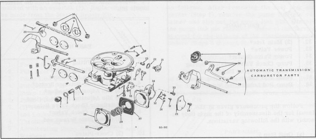
Figure 4.
Disassembly-Throttle Body
revisions to the given procedures.
(a) Steps 6, 10, 11, 12, 13, 14, 16, 17, 18, 19, and 20 in the Service Manual are to be disregarded. They are not applicable for the 1954 applications of this carburetor.
(b) Step 9 is to be revised as follows: Remove the secondary throttle rod retainer, washer, and rod pin and slip out the secondary throttle rod. Discard the retainer and pin.
(c) After completion of Step 22 in the Service Manual, remove the diaphragm housing cover screw and lockwasher and lift off the diaphragm housing cover.
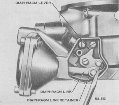
Figure 5. Removing Diaphragm Link Retainer (d) Remove the diaphragm link retainer.
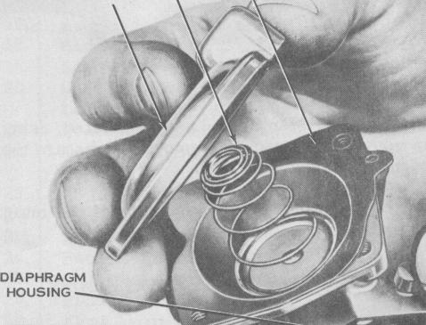
(e) Hold the diaphragm cover in place and remove the four diaphragm cover screws and lockwashers. Remove the diaphragm cover and diaphragm spring.
(f) Slip the diaphragm link off the diaphragm link pin and ease the diaphragm and link assembly out of the diaphragm housing. Discard the diaphragm and link assembly.
(g) Remove the diaphragm lever screw and lockwasher from the end of the secondary throttle shaft. Remove the diaphragm lever.
DIAPHRAGM AND LINK ASSEMBLY
DIAPHRAGM SPRING
DIAPHRAGM COVER
S4-514
Figure 6. Removing Diaphragm Cover
-12