(a) Step 4 is not applicable and should be dis regarded. Revise the procedure for Step 2 as follows: Using a new pump link retainer, install a new pump link on the primary throttle lever.
(b) Place the new accelerating pump rod felt seal and the two washers in position between the main and throttle bodies. Carefully ease the accelerating pump rod down into position. Hold the rod in that position and engage the pump link, using a new pump link pin and new retainer.
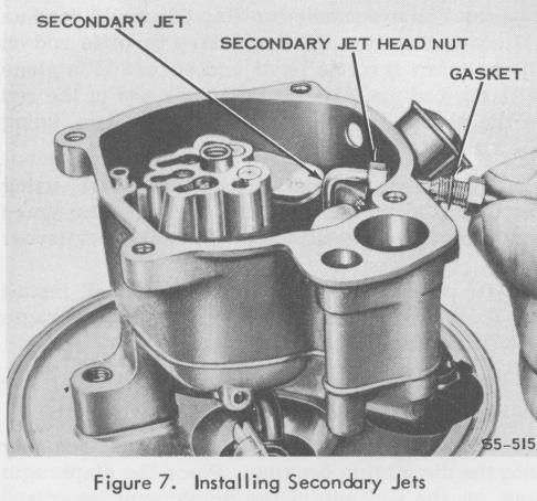
(c) Install the two new secondary jets, using new head nuts and gaskets. (Place the gasket next to the head of the jet outside of the main body casting).
(d) Complete the reassembly (Steps 3 through 6) as described in the Service Manual.
INSTALLATION
1. PREPARATION
Check the carburetor as described in the Service Manual.
If the carburetor being overhauled is equipped with a dashpot, the following procedure is to be used to adjust the dashpot.
2. INSTALLATION
B. ADJUSTING THE DASHPOT
Follow the installation procedure given in the Service Manual.
3. ADJUSTMENTS
(a) Start the engine and allow it to reach its normal operating temperature. On engines equipped with automatic transmissions, the drive selector should be set at "neutral".
Adjust the idle and the automatic choke as described in the Service Manual. Disregard the procedures given for adjusting the secondary throttle plate opening and for adjusting the mechanical spark advance (Steps C and D). Use the following procedure for adjusting the secondary throttle plates if they have been removed for any reason.
A. ADJUSTINGTHE SECONDARY THROTTLE PLATES
Place a .005" to .006" shim (the shim should be about 1/8" wide) between the leading edge of the secondary throttle plates and the throttle bore. Close the throttle plates fully and, with the shim still in place, tighten the throttle plate screws securely.
IMPORTANT
The shim must be used when adjusting the secondary throttle plates to insure a consistant idle.
(b) When the normal operating temperature has been reached, allow the engine to idle. Turn in the dashpot adjusting screw until it no longer compresses the dashpot stem. It is important that the adjusting screw does not interfere with the normal idle setting of the carburetor. If the adjusting screw prevents the throttle lever from reaching the idle position, an excessive idle speed will result. It will then be impossible to obtain an accurate idle speed adjustment.
(c) Set the idle speed and mixture according to the instructions in the Service Manual. Check to insure that the idle speed screw is on the low step of the fast idle cam.
(d) Set the dashpot adjusting screw to obtain the specified clearance between the adjusting screw and the dashpot stem. This setting should be made with the dashpot stem in the fully compressed position. Refer to the current Holley Carburetor Catalog sheet for this carburetor for the proper dashpot clearance.
-14-